- Get link
- X
- Other Apps
- Get link
- X
- Other Apps
1. Fused Deposition Modelling
Fused Deposition Modelling (FDM) was developed by S. Scott Crump in the late 1980s and was commercialized in 1990 by Stratasys. As the name suggests, the parts are formed by deposition of the fused material in layers. The working principle of FDM combines seven key points:
Material loading
Material melting
Extrusion
Solidification
Position control
Material bonding
Support structures
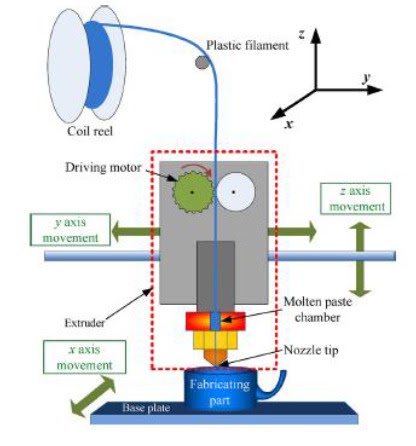
Plastic filament material from the coil reel is extracted with the help of a nozzle assisted by a gantry robot. This guidance provided to the nozzle helps it move in the X-Y plane. The extracted material from the coil is melted and evenly distributed by the nozzle in the form of molten paste on the vertically moving table. A predefined path is mapped out according to the design of the component and the nozzle follows this toolpath in a layer-by-layer approach. After the first layer is formed, the table lowers down accordingly with the layer thickness and hence, subsequent layers are built in a similar manner of operations as demonstrated in Figure 1.
In order to build complex components, additional support materials can be used along with building materials. These are used to give support to the overhanging parts of objects during the printing process. These support materials are removed by melting or by breaking after the main component is solidified at the end of the process.
The materials used in the FDM process are generally thermoplastics which are available in filament form for extrusion and deposition. Acrylonitrile Butadiene Styrene (ABS) and Polylactide (PLC) thermoplastics are predominantly used in FDM. Components with complex geometrical designs could be easily manufactured with 0.5% dimensional tolerances.
2. Digital Light Processing
Digital Light Processing (DLP) based 3D printing technique comes from the Image Projection technology developed by Texas Instruments in the 1980s. In this printing method, a 3D model created in the CAD software is sliced digitally to form the digital geometric tool paths for the DLP printer.
Thereafter, the DLP projection system projects the first layer image on the transparent basin which contains photopolymer and the U.V. light is incident on this basin. These photopolymer resins undergo a photopolymerization process when exposed to UV light of wavelength 360-420nm. The main functional part is a Digital Micromirror Device (DMD) which comprises a group of micron-sized, controllable mirrors as represented in Figure 2. These mirrors rotate to control the path of light with respect to the model. When light is projected onto the photosensitive resin using DLP technology, instead of being restricted to a spot like laser-assisted 3D printing, the entire layer is printed straightaway. After the first layer is formed, the stepper motor moves the basin accordingly as the process is repeated till the completion of printing the 3D object.
 |
| Figure 2. (a) Schematic of 3D DLP printer; (b) DLP 3D printing approach [Source:https://link.springer.com/chapter/10.1007%2F978-981-15-7827-4_67] |
Liquid Photopolymer resin is used as a raw material in the DLP 3D printer. There are several resins available in the market such as Maker juice G+ resin and Fun to Do resins.
Basic Comparisons
Research presented for the Fused Deposition Modelling (FDM) technique concludes that there are several parameters directly influencing the quality of the FDM parts some of which include temperature, speed, infill density, layer height and build orientation. Hence, further research in this method can greatly improvise the textures and details of objects printed using FDM. Furthermore, because of the exhaustive energy, fast cooling, and phase transformations, parts manufactured by FDM deviate from the intended geometry, and some parts need lengthy post-processing. Therefore, the SLS technique is preferred over the SLA and FDM techniques to fabricate objects with geometrically complex designs.
Unlike FDM, Digital Light Processing (DLP) is a light-based printer that uses a light beam to process the resins under high temperatures. Hence, the DLP technique has a relatively higher fabrication speed and it fabricates objects with a higher resolution on a micron-scale which a nozzle-based printing method such as FDM cannot perform.
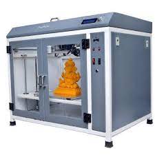
Visual representation of typical FDM and DLP printers are illustrated as under:
 |
| Figure 3. FDM 3D printer by Make3D Co. |
 |
| Figure 4. DLP 3D printer by Flashforge Co. |
- Get link
- X
- Other Apps
Comments

Is there any way to use waste plastic as a input instead of plastic coil reel?
ReplyDeleteYes, there are some research papers which explain how the post-processing waste plastic can be recycled and reused by sorting, shredding and extrusion processes. A research paper from 2015 published on this specific subject can be found on Reseachgate.
Delete